The Diesel Flyer 20/58 and its variations. Information about repair and spare parts.
Many thanks to Garry Lefevre who helped with this translation and made the photos of the version 1 and 7.
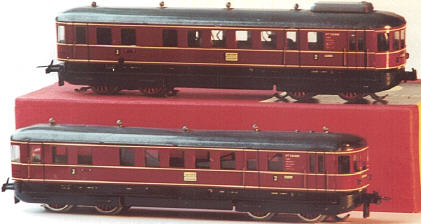
The production started in 1937 of the German Trix Express motor coach ( "Triebwagen" - after the war re-launched as the Diesel Flyer for the English market). It was advertised as a scale model like its companions the Pacific 20/57 and 20/59. Compared to the toy-like design of the first 0-4-0 locos the introduction of this scale models was a big step forward in the development of gauge 00 model railways. No doubt about it - the 20/58 is one of the most handsome models of motorised coaches ever made for that scale. Running it on layouts at exhibitions it is always a top event. Is it because of the perfect design, the massive sound when running at high speed or is it the red and white lights which change when reversing? It is most impressive when running in the dark on a fully illuminated layout surrounded by old tinplate stations and platforms. Together with a lightened Märklin ST800 probably the maximum an operator at the control of an historical layout can show to his audience.
Variations on the 20/58
The 20/58 exists in a lot of variations, which never have been completely documented in literature. Therefore a fuller description is given here:
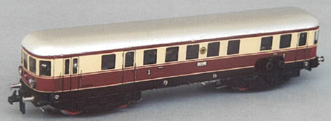
Version 1 from 1937 has short silver buffers, thick diecast couplings front and rear. Motorcoach and trailer show the German State Eagle symbol in the middle of the coach between two windows. Bogies have diecast holders on both sides, 3mm axles and wheels on plastic bushes which easily can be removed. The interior motor layout and reversing mechanism is based on the English TTR Southern Portsmouth motor unit. The cable between the motor unit and trailer coach comes through one hole in the latter with a two pin connector into the motor unit. This first version had reversing lights with the colour being 2 reds and 1 colourless light bulb at tail and front respectively. The reversing mechanism has the old large 4 star style gear wheel. This version is most sought by collectors.
Version 2 from 1938, is like version 1 but now holders on the bogie were made from tinplate sheet which is held in place by screws. The cable is now connected via twin pins between both units. The lights too were changed to the familiar 2 colourless and 1 red bulb. The reversing mechanism now has the new gear wheel but still without the spring bar above the reversing arm.
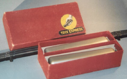
Version 3 from 1939, is like version 2 but now long silver buffers were fitted and the new coupling which can be remotely uncoupled by an uncoupling rail which was designed in the same period. New is also the spring bar above the gear wheel of the reversing mechanism to assist the falling back of the reversing pawl. All pre-war versions were sold in the buff coloured box, most of them with the label from 1937.
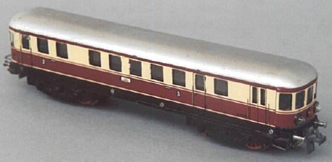
Version 4 was sold after the war, probably from 1948 on. Parts from pre-war production were still used. So these models very often came along with the coach side showing the Eagle on the motor coach while not having this on the trailer coach. Long silver buffers and new coupling like version 3 were fitted. Sometimes one comes across items which have bogies with 3mm and the new 2,5mm axles mixed on one unit. The poor times after the war necessitated a lot of compromises. It is likely that these versions were still sold in the old pre-war box with the 1937 series label on it. Were they from the remaining stock from the old huge production runs which survived the war? Who knows. At least I am sure that the label printed in the 1937 series must still have been sold for some period after the war as I found an original boxed post war item forgotten in a loft where post production changes can be excluded. Sometimes this confuses collectors. Also it is possible there are replacement models which were sent back by complaining customers whose models suffered pre-war fatigue or otherwise were damaged. This might explain some of the blending of pre- and post war parts.
Version 5 cannot be dated exactly, probably simple stock clearance of pre-war parts at the Trix warehouse explains the various changes to pure post war models. Both units were now without the Eagle, all bogies were with tinplate holders, only 2,5mm axles, all wheels mounted on brass bushes which can not be removed easily by using a wheel puller, instead one needs to cut them off carefully. These were only sold in the post war red box.
Version 6 is the so called Diesel Flyer which was sold after the war from 1951 till 1953 in the UK although still being manufactured in Germany. The red box had the label "Diesel Flier", wrongly spelt. No Eagle of course and unlike the German model there were no couplings at both ends as there was no use for it to couple to any other wagon from the TTR range. It also would not fit well to the post war Peco style coupling.
Version 7 is the last production run from 1953 before Trix changed to DC technology. The roofs of both units were now grey instead of silver. Sold in the same red box. Very rare version. There also was an english version of the Diesel Flyer exportet to the UK missing the end-couplings and in the english labelled red box.
After the 20/58 production ceased the new TE 758 was introduced as a two coach motorised unit. It had a changed design with the new rebuilt permamotor. This motor was based on the old AC engine having the electromagnet of the motor cut off and a permanent magnet glued in instead. This motor was never produced in England as they changed in the later fifties directly from AC to the new DC motor which was a completely new design. Gone was the familiar red and cream coach colours instead it was now red only on a new streamlined chassis, improved fatigue free nickel-plated wheels fitted with traction tyres and vents in the roof of both units which sometimes come loose and get lost over the years. No cable connecting the model was necessary as DC diodes were used to change the lights over. The light change was less fascinating because of the use of transparent plastic light conductors instead of single light bulbs. These are excellent runners as they don't reverse unexpectedly and have really improved pulling characteristics.
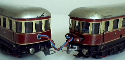
above: The connection cable of version 1. A single hole is in the trailer and the plug goes into the motor unit. The plastic cable is not original and the matching one often needs repair after all the years. Unfortunately the cotton covered brown cable is not available as replacement part today.
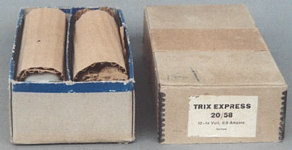
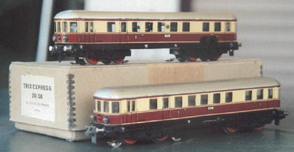
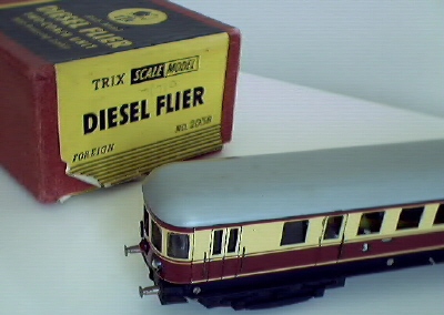
obove: version4 still sold in the pre-war box
below: version 4 in front of its original box
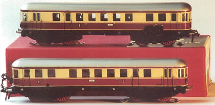
above: motor unit version 4 with State Eagle
below: trailer belonging to the same model, no State Eagle
above: version 5 in the red post-war box
below: version 5 with brass bushes, one can see the result of fatigue on the wheels. Very often all wheels need replacement. I recommend mazak-wheels from TTRCA. They show the best running characteristics and good traction.
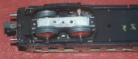
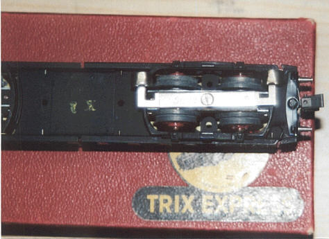
above: Trailer bogie with collector shoes. The mark "K1" states the production run being done in month K (which is the October of a year). The number 1 stands for 1951.
below: Version 6, the English Diesel Flyer, no eagle and no end-couplings.
below: Version 7 in the english export version and its english labelled red postwar box.
underneath: The DC TE 758 with the rebuilt Permamotor.
Restoration of the 20/58
Repairs to the 20/58 is no simple matter. It should only be attempted once one has sufficient experience with more uncomplicated models. All replacement parts should be examined to make sure they fit before mounting. The following damages are frequent:
Wheels : Because of metal fatigue these often decompose or at least become loose on the axels.
Repair: If it is an early version with wheels on plastic bushes, it could be only the plastic has shrunk and the wheel itself is still intact. Then the wheel can be fixed with superglue. An alternative is to place a small piece of cotton thread between the wheel and the bush, pressing the wheel back onto the bush. Afterwards the surplus cotton can be cut off. However the most common fault is the wheels themselves suffer from metal fatigue, especially the post war version. Then the only cure is to change the wheels. The wheels of the 20/58 is more narrow than those of the simple 0-4-0 locos which can not be used for the 20/58 due to insufficient clearance with the side frame which can cause electrical shorts. Therefore one needs necessarily narrow wheels. Franz Nowack offers this casting. The wheels turned on a lathe are also very precisely made and run in action very smoothly. However, as an alternative I recommend the English TTRCA wheels made out of Mazak (also available from Franz Nowack or Marin Drayson of the TTRCA in England). These certainly can be used also for the English of 0-4-0 locos, since they are sufficient narrow. These replacement wheels incorporate diecast gear teeth and not a separate gear tooth made from metal sheet like those on the original 20/58. However one only sees this, if one views the model from underneath. The Mazak-wheels are very exact and have especially good grip on the rails. The 20/58 inclines anyway to wheel spin, because it doesn't have any traction tyres. In use the diecast wheels can slip if the gears do not mesh properly causing poor running. Therefore each time I suggest to change the Mazak-wheels on both the drive axels if the originals are damaged. For the Mazak wheels there are special bushes, that one must file off being careful not to go through the axel. If the wheels are on brass bushes (post-war-version), one can cut open and take off. The track-width must be correct at 15.5 mm between the wheel flanges measured across the track! One can adjust them by putting on plastic washers on the axels. The axels must have no big side movement, otherwise the wheel cogs will not run smoothly through the reduction gear and can jam or get into contact to the bogie frame what can cause an electrical short.
Bogie mounting frame can decompose or break
Repair: It could have metal fatigue in the bogie outer frame or the bogie chassis itself. The outer frame one might be able to glue, but the bogie chassis if it has grown will often jam. It is best then to make a total exchange of the bogie chassis - please proceed carefully as sometimes a grown bogie chassis has bent the outer frame and bending back can cause damage. The early version has diecast pieces instead of metal sheets. If one only can get the early bogie chassis then one can file them gently to fit again and put back the sheet metal-parts after making the tread for the screws. The screw-tap is insulated from the motor body. There must not be any contact between this screw or the interior-part to the axels or the turning frame itself. This type of electrical short circuit is difficult to localize. Put emergency thin plastic-strip in between. Note carefully the cable-connections. A drawing will help. One can put in also little plastic-screws, to hold in place the shoes - that is a sure solution.
Motor side frame decomposes
Repair: The motor side frame with the brush mountings is made of two parts. The outer visible part is metal whilst the inner part is an insulating material. When replacing this part be careful not to throw away the entire broken part as the replacement part comes without the insulation material and the older material can be reused. Get a new motor side frame and adjust it. One could use the normal frame of the 0-4-0, however the ends must be bevelled, because otherwise the casting hinders the bogie movement on curves. Instead of the rivets I make 2mm holes with a screw tap and put small screws in and file the head flat. It then looks just like rivets, holds well and does not damage the soft material on the inside of the mounting. The insulation material on the inside can be super glued in place if needed as it should not be able to bend. Your aim is to have a level finish so the motor brushes have the same pressure otherwise they can wear more quickly or the motor not function correctly.
Motor rigid or without apparent electrical contact
Repair: Everything should be stripped down and thoroughly cleaned, suitably oiled, and assembled. Warning: never oil any part of the contact shaft. Also be careful that the thin wires on the armature are not damaged. If the armature has been put in crooked it is possible that some wires have been damaged by rubbing against the casing. They can be repaired by rewinding the armatures but this is not a job for the amateur. We have specialists in the TTRCA doing that job very precise. Before re-assembling check all cables and contacts make a good electrical connection. Worn motor brushes can be replaced either using motor brushes made by Märklin ( 800er/ 3000er series works) or purchasing replacements via the English TTRCA. Also the small spring in the brush holder may need replacing which can be obtained from the TTRCA or Franz Nowack. Always I overhaul the motor before replacing new wheels, because the armature is easier to move in and out without the wheels in place.
Reverse not functioning
Repair: No part of the reversing mechanism should be oiled, because it can then stick. It must fall back loosely. The contact shaft might receive only a very tiny amount of oil on the parts holding it in place. A sheet metal part is pulled by the electromagnet towards it, which turns the gear one position and the contact shaft one turn. If the gear is worn out or has decomposed replace it. The reversing pawl can also sometimes be brittle. These parts can be reconstructed or taken off another motor. One can often spend a lot of time adjusting these mechanics to get them working just right. Where the metal arm makes contact with the magnet over many years this can become pitted. The solution is to sand or very finely file the two surfaces where contact is made, this prevents sticking. The spring bar above the reversing arm assists the falling back of the reversing pawl. But this is missing on the earlier versions which means the reversing mechanism is even more dependent on being very clean and accurately assembled. The 20/58 mechanism described above is for version 2 and after. The first version can be distinguished by the large 4 star style gear wheel on the end on the contact shaft.
Problems with the electrical short circuits
Shall we take a bet: The "Short" is in the motor assembly? Is there any axle or wheel in contact with each other ? Investigate the pick up shoe. Does the screw have a short to the body? Does the sheet metal-strip (the interior into the body under the axles) have contact with the axels, because it has bent? Is the connection-cable to the trailer coach O.K.? These are just a few clues.
Badly marked and scarred roof
Repair : To remove the roof carefully partly bend the tabs back, these can break off so only partly bend them back. However the roof may just need re-varnishing, on the pre-war variation with shellac coats (because of the patina). If in very poor condition, the roof can be completely repainted. This is best done first by stripping off the old paint. Spraying the roof with a silver paint and whilst wet passing quickly and lightly over it with a gold spray. The final dry roof can then have a spray varnish applied. This gives a similar patina effect to the older pre-war version. It needs some practice to get the final light gold spray just right. One can practice on old metal or cardboard !
Window celluloid inserts can be broken or missing.
Repair: Cut out new plastic inserts either from sheets from a model shop or from envelopes !
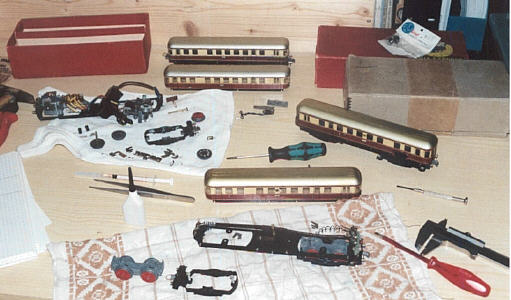
above: Typical scene on my work bench. Christmas 2001 I had 3 models of the 20/58 to be restored. This was an absolute coincidence, because one finds them so rarely any more. The one in the front is the version 2 of the pre-war production.
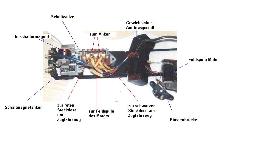
below: The reversing mechanism with explanations. Impressive, how complicated it was to enable the light-change from colorless to red.